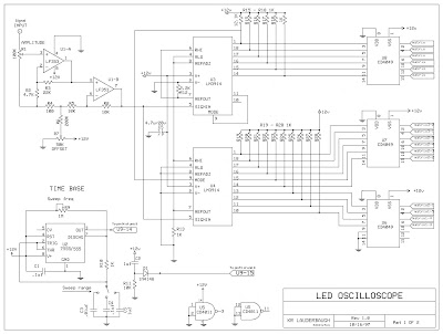
Here I post the original schematics of LED oscilloscope, there are a few mistakes regarding to some ICs +/- connections, and also at the connections from U3, U4 toward U6 and U8 which they not make any sense!
I did not had time to check these mistakes, so please look for your self before you connect any power source to the circuit. If it is too confusing, you can always email or PM me here, I will try to help ASAP.
U1 LF353 (op amp) didn't work for me, I had to change it with some other op amp ICs, like LM1458/1558 or LM158/258/358 which all are Pin compatible with LF353.
Edit: (20-05-2012)
Finally I find some time to fix all the mistakes at the schematics, and I hope that all are OK now. If you
find a new mistake please send me a message so I could correct it. Thank you for your attentions.
Remember that, the original schematics are for 9 x (5x7 LED module) 15 vertical (rows) x 21 horizontal
(columns) LEDs, where my scop has 6 x (8x8 LED modules) 16 vertical (columns) x 24 horizontal (rows)
LEDs (as this schematic are now)


6 comments:
will there be an update to these schematics soon to filter out all wrongs
thx
Yes, I will try to update the schematics very soon, sometimes in this week.
Thankfulness to my father who told me concerning this blog, this
webpage is truly awesome.
My page: good Anniversary Gifts
I'm truly enjoying the design and layout of your website. It's a very
easy on the eyes which makes it much more enjoyable for
me to come here and visit more often. Did you hire out a designer
to create your theme? Exceptional work!
my page :: Childcare fullerton
Thank you everyone for your nice words :)
Nice work , I love your led driver circuit :)
Post a Comment